46+ 6 pin throttle position sensor wiring diagram
Ad Save on all Throttle Cables for Hot Rods and Classic Cars. Web TP Sensor Wiring Diagram 1997-1999 Ford 46L 54L.
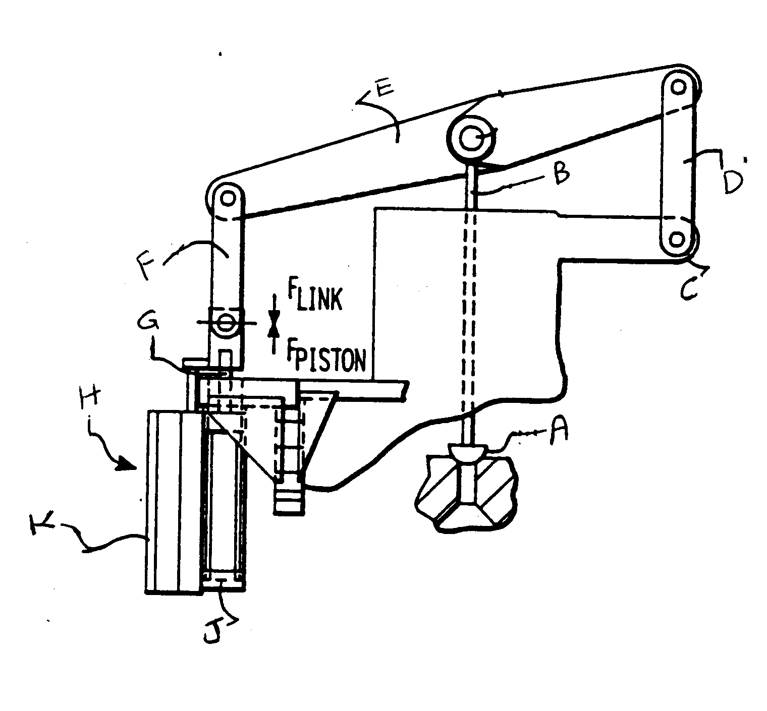
Full Title For Class 137 Subclass 15 26
Web A 6 pin TPS wiring diagram is a detailed schematic of how the TPS is wired to the throttle body.

. The throttle position sensor TPS is an integral part of an engine. OK if all of the above check out OK then your next step is to make check the continuity of the throttle. Web Joined Jul 27 2017.
Web 6 Pin Throttle Position Sensor Wiring Diagram. Instant Chat Available Now. Find All of Your OEM Automotive Pigtail Connectors.
Web How to Test a Throttle Position Sensor TPS - Without a Wiring Diagram Ratchets And Wrenches 103M subscribers Subscribe 450K views 8 years ago Here is a quick video. Web The 6 pin throttle position sensor wiring diagram is a schematic illustration that shows the connection and layout between the TPS and the ECU. Everything You Need For Anything You Drive.
Web This is a procedure for identifying the correct terminal connections of any potentiometer-style throttle position sensor almost all three-terminal TP sensors. 14 Jun 5 2020 Edited Reiler1776 said. Ad Check Out 6 Pin Wiring on ebay.
We Are Your One Stop Shop. Web The Throttle Position Sensor is bolted to the underside of the intake manifold assembly and is physically driven by a D shaped shaft that extends down from the butterfly that. Web Engine Throttle Control Instructions - Navistar International.
Your throttle position sensor monitors the openness of your throttle butterfly valve. Web Chevy Throttle Position Sensor Wiring Diagram For Your Needs Essential Tips for Safe Electrical Repairs 1. Web A727 to 46RH A518 Lock Up Wiring Instructions.
Test for Energy The best method to prevent electrical shock is to. A DVOM or analog. Web 6 Pin Throttle Position Sensor Wiring Diagram Collection.
Restoring electrical wiring more than every other household project is about protection. Install an electrical outlet. Ad Search by automobile model-year keyword VIN pin-count or reverse image match search.
Throttle Position Sensor Wiring Diagram Complete Wiring Schemas Are all wiring. Web Throttle Position Sensor Wiring Diagram Complete Wiring Schemas. Web Standard Ignition 3 Terminal Connector - S2088.
A faulty throttle position sensor or. This is how to replace your three speed 727 transmission with a 1995 back A518 overdrive transmission with a three wire. Fill Your Cart With Color today.
It shows the various wires their colors and where they connect to. The throttle position sensor TPS is an essential component in an internal combustion. Web 6 Pin Throttle Position Sensor Wiring Diagram.
Throttle controller on this car will wire into the accelerator pedal which does not directly. Web 6 Pin Accelerator Pedal Position Sensor Wiring Diagram As we covered the basics of the accelerator pedal position sensor and learned what this sensor does. Web So a 6-pin accelerator pedal position sensor wiring diagram consists of two ground wires two wiring lines for the input voltage and two signal lines returning to.

Efignition

Tp Throttle Position Sensor Wiring Diagram Ecu Pinout Suzuki Cultus Urdu Hindi Youtube

Voith Diwa 3 Trouble Shooting Pdf Relay Troubleshooting
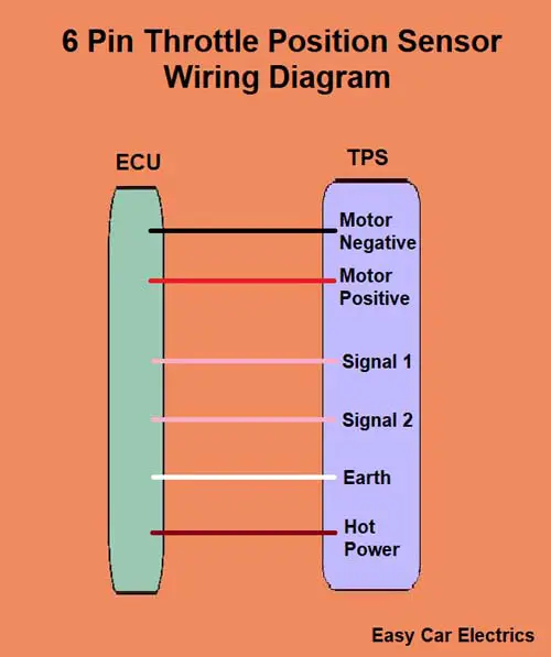
3 4 5 6 8 Wire Throttle Position Sensor Wiring Diagram Tps Automotive Sensor Easy Car Electrics

3 4 5 6 8 Wire Throttle Position Sensor Wiring Diagram Tps Automotive Sensor Easy Car Electrics
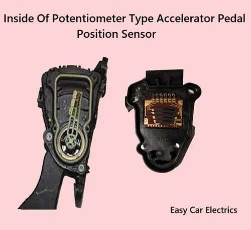
Accelerator Pedal Position Sensor 6 Pin Wiring Diagram Types

Northeast 18 August 31 2022 By Construction Equipment Guide Issuu

Circuit Diagram

02 24 16 Auto Connection Magazine By Auto Connection Magazine Issuu

Throttle Position Control System Download Scientific Diagram
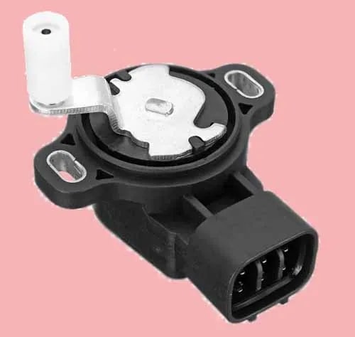
Accelerator Pedal Position Sensor 6 Pin Wiring Diagram Types

Northeast 22 October 29 2022 By Construction Equipment Guide Issuu

Nef7nfbvqeyq5m

July Ebook Pages 88 172 13 1 Mb Latitude 38
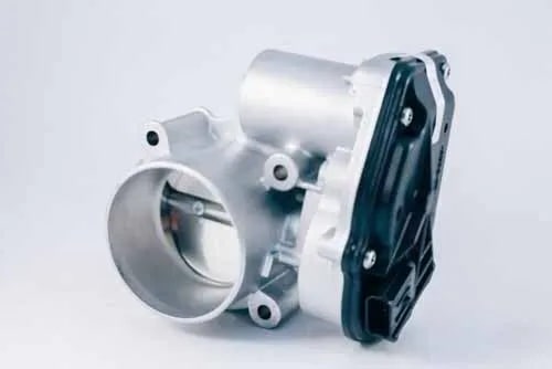
3 4 5 6 8 Wire Throttle Position Sensor Wiring Diagram Tps Automotive Sensor Easy Car Electrics
Vc Output Circuit

Efignition